Can I flash tasmota or esphome firmware?
What if I later want to restore original firmware?
2 Likes
Yes you can flash but that will void warranty and support. We do not provide any kind of support on this. This forum will be your only help.
No, you won’t be able to flash it again . We don’t be able to share tinxy firmware. We could do it for a fee if you ship it to us.
If you choose to do it anyways. Here is some information.
For 1N , GPIO4 is the relay pin
For 2N, 4N, 6N , you must un-short W2 and W3 bridges . W2 and W3 connects the TX RX lines of ESP8266 to the MCU . If they are connected they will interfere with programming ESP. You must un-short, when done you must short it again for ESP to send serial comm to the MCU
ESP8266 12E sends Serial at Baud rate 9600 (old model) and 115200 (newer models). Examples of Serial TX
#1100# turn on relay 1
#1000# turn off relay 1
#2100# turn on relay 2
#1033# set fan speed to low for 1N & 4N fan only
#1066# set fan speed to low for 1N & 4N fan only
Serial RX
;11; Switch 1 turned ON
;10; Switch 1 turned OFF
;21; Switch 2 turned ON
;13; Fan speed set low by manual fan regulator
;14; Fan speed set medium by manual fan regulator
;15; Fan speed set high by manual fan regulator
Hope this helps.
Mohit
5 Likes
Thank you Mohit for the information.
Hi - Can you tel me which GPIOs are in use for Relays? Also with 4 node model with Fan - how are you controlling fan speed…i see only 4 relays …I want to flash this with esphome which is why i am asking
Everything is mentioned above.
Pardon my knowledge… i didnt understand…what does it mean by #1100# ?? Is that Mqtt payload?? Also above only for one 1N GPIO4 is mentioned … what about 4N??
@mohit or if someone help - without knowledege of Relay pin connection i am not able to write my firmware…
Updated my comment . Please see above
I still dont get … i am so sorry… i no electronic expert but a hobbyist…i need simple pin connections between esp8266 to Relay. 
Hello Raj,
As you are hobbyist, simplest thing you can do are:
- Take multimeter and trace paths. 4 relays and 4 switch will not take much.
Or
- Go with trial and error. With tasmota, it would be dam easy. Make all relay ones and see which works when. Next make all switch and sww which works when.
WIll give this shot…
Expect 1N, all other smart switches are connected to another MCU with serial communication. Here you can learn more about it.
")
Hi Mohit/Members,
I am also a hobbiest and want to use NodeMCU to flash tasmota on the 2N tinxy board. I have got some information on connecting NodeMCU to onboard 8266.
Could you please help me by sharing any information that I have to take care of while doing this?
I have flashed tasmota successfully on the esp chip of 2N tinxy board. Will try to send serial data to another MC to check relay control
Can you help me to share the connections done from Node to Tinxy.
I am trying same, help me identify the connections or share the article which you referred.
You can follow method 3 from this link - 3 Simple Ways of Programming an ESP8266 12X Module - Hackster.io
2N board already has provision to solder 5 pin header connector for following -
VCC
RST
RX
TX
GND
Additionally, connect D3 of NodeMCU to GPIO0 of ESP8266. No additional connection required
Serial communication with another MCU done successfully. When manual switch is used , other MCU turned relay on/off and sent serial response to esp8266 indicating manual switching.
For 2N board noticed something, manual switch connector L1 generated ;21; or ;20;; while L2 generated ;11; or ;10; as serial response. Shouldn’t it be opposite?
I am getting “timed out waiting for packet header”, do we need to use the the passive components(reg’s and caps) as given in below circuit?
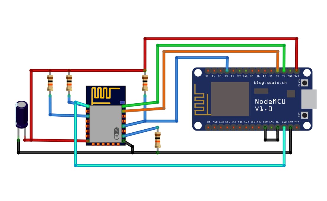
I forgot to tell about this error. The TX and RX header pin is actually connected to both chips esp8266 and the other one that controls the relay. This is required for serial communication between both chips. To flash, you have to break this connection. If you look closely on the back, you would find the point from where to take the soldered wire off to make it work. After flashing, reconnect them else relays won’t work.
1 Like
I am a beginner in hardware and electronics.
For controlling the relay I am writing the command
#1000# - Turn off Relay 1
#1100# - Turn on Relay 1,
using the Serial.write( ) method
ex. Serial.write("#1000#") at baud rate 9600.
Serial.write("#1100#") at baud rate 9600.
but the relay is not turning on or off depending on the command
Plz Help