I am following this thread closely. Can anyone help to share steps for hardware preperation to install tasmota?
I am aware of general process of flashing and subsequent webui setup but thanks to my poor soldering skills, I am confused on steps to make tinxy device recognizable in flash program.
I do have an idea for a way to do it but I am yet to try the idea out in practice. It would take me a few months before I actually and sit down to work on this though.
Can someone guide in preparing a 2N & 4N device for flashing custom firmware?
I have followed the steps mentioned in the post above including breaking the RX/TX connection to MCU but still not able to get the device into flash mode.
@amitxin I am stuck at trying to connect Tinxy 6N to FTDI controller to flash Tasmota on it. I have connected GND → GND, RX → TX, TX → RX & VCC → VCC (3,3v) in FTDI to Tinxy.
After connecting, holding the reset button on Tinxy and plugging the FTDI to computer and trying to flash Tasmota, Tasmotizer is still stuck at “connecting”?
Question:
How put Tinxy 6N (and also 4N and 1N) to debug mode? Is holding given reset button on Tinxy enough when plugging in FTDI controller?
From the above discussion, there is a point about connecting D3 to GPIO0? Is this required?
If so, there are 2 D3 marking on the Tinxy 6N. One on the small sister board, Another D3 on the back of the main board.
Also, D3 has +ve and -ve. To which terminal of D3 should I connect with GPIO0? (I assume -ve).
And should this connection be connected for the duration of the flashing or only to enter debug mode.
There is also another point about desoldering RX/TX pin between 2 boards for flashing and reconnecting after flashing? Is this also required? If so, can someone provide more details about what to desolder?
I have bought couple of Tinxy devices and would like to connect to HomeAssistant. Would really appreciate the help.
I use CH340 based programmer (used to flash ESP-01), So I connect GND → GND, Tx → Tx, Rx → Rx & Vcc → Vcc (3.3). Uses Arduino serial monitor check the logs (without connecting to main power supply).
To upload the custom firmware, connects the GPIO0 to GND (via 10K), then connects the Vcc and you can see the ESP is in flash mode on serial monitor window, close the serial monitor window and upload the firmware. Mostly, the connection between GPIO0 and GND is required only to access flash mode, once it is flash mode you can disconnect it continue with flashing.
Point 3: yes you need to disconnect the serial communication between ESP and other MCU. After flashing, you have to connect it back.
I am trying to flash 16A 1N with Tasmota/ESPHome, but the module keeps on restarting every 30-40 seconds. Works fine when connected to serial via RX,TX,G,VCC. I really need to use custom firmware for my home automation. Please help
Please be more specific on this. What is the frequency needed for the pwm signal? Assuming it has to be done right after hardware initialization till wifi setup.
Guys, Just posting my fix here for the esp restart. For esphome users, this should fix the reboot issue. The key is, it should be at priority 200. on_boot documentation for reference
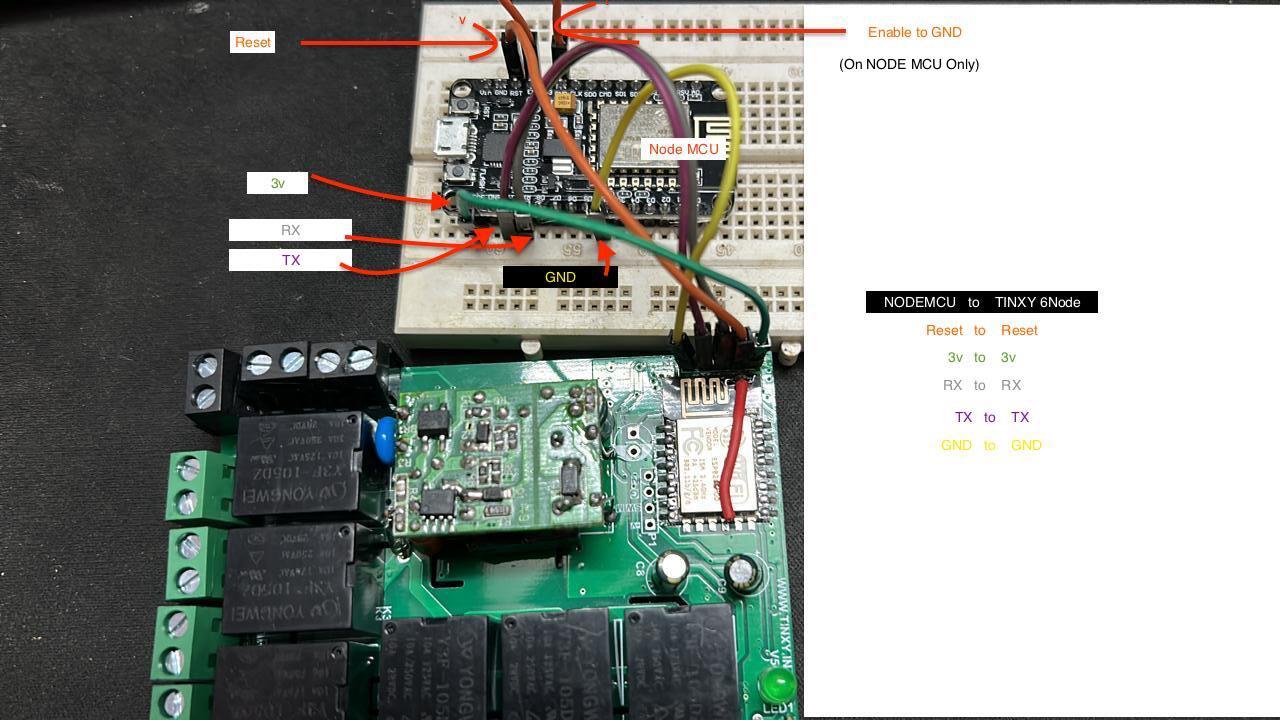
Hi @b6e7i9 , I’m trying to flash my custom esphome firmware on Tinxy 6 Node module, but I’m unable to do so. I think I’m messing up with pin connection somewhere. Can you help me in finding what I’m doing wrong?
Sharing you an image of my connection setup.
I’m using Node MCU to flash the esp 12e onboard. I’m using Arduino IDE for flashing.
Hi @mohit@b6e7i9 , thanks for letting me know about the USB to TTL converter. I bought it and followed the steps. Unfortunately, I’m not able to flash it. I have few questions -
a) Is it necessary to use resistors and capacitors to in the circuit to make flashing possible?
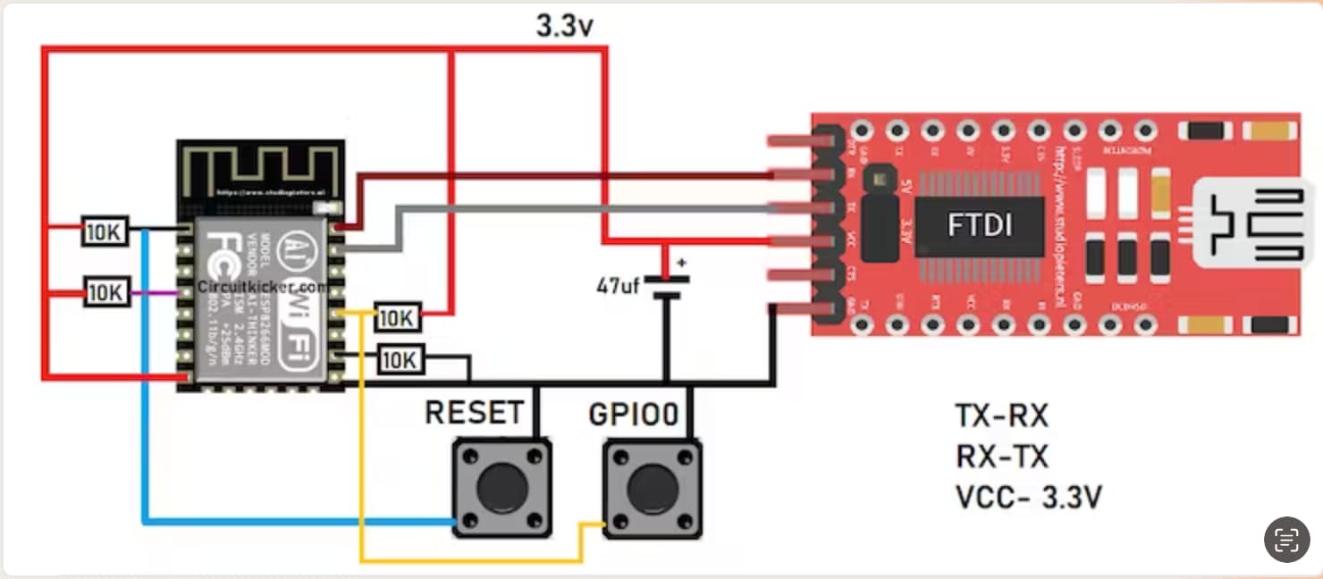
b) Is the diagram mentioned below good enough to follow, or am I wrong here? If so, can you please share me a proper tutorial to guide. The one which you shared above is for ESP8266 01 model, in which the pins are quite different from the Esp 12 series which the Tinxy device is using. I’m using Arduino IDE for flashing, and I’ve tried both “NodeMCU 12e board” and “Generic Esp8266 board”. Both of them were unsuccessful.
c) Also, do I need to make any changes to the 4node & 6node circuit board before flashing? I’m asking this because above few people mentioned that we need to unsolder RX-TX pins. But when I looked at the circuit, I couldn’t find any.
d) Would you terribly mind creating a Youtube video explain the connections and flashing mechanism, so that this entire Thread will benefit from it and lessen the confusion.