Hi @mohit and others - I’m trying to flash Tasmota on a 2 node Tinxy (using a USB to serial TTL converter). I un-shorted the W2 and W3 as instructed. When I try to flash Tasmota (tried multiple tools) though it looks like my device is connected, but the flash fails with a message “Invalid head of pin 0x72”. Any clue on what might be wrong?
Hi, I recently bought a Tinxy 4N with Fan module, flashed it with ESPHome code from @b6e7i9 . Also got the fan regulator working. But the wall switch position sensor for all the four relays stays as unknown no matter how I toggle the physical switch. What I am doing wrong?
Is this something to do with baud rate?
esphome:
  name: tinxy-4node
  friendly_name: tinxy-4node
  on_boot:
    - priority: 200.0
      then:
        - output.turn_on: gen_pwm_test
        - output.set_level:
            id: gen_pwm_test
            level: 50%
  includes:
    - uart_read_line_sensor.h

output:
  - platform: esp8266_pwm
    id: gen_pwm_test
    pin: GPIO14
    frequency: 1000 Hz

  - platform: template
    id: fanoutput
    type: float
    write_action:
    - uart.write: ""


esp8266:
  board: esp01_1m

# Enable logging
logger:
  baud_rate: 0
  level: VERBOSE

# Enable Home Assistant API
api:
  encryption:
    key:

ota:
  password:

wifi:


status_led:
  pin:
    number: GPIO12
    inverted: yes

uart:
  id: uart_bus
  tx_pin: 1
  rx_pin: 3
  baud_rate: 9600

text_sensor:
  - platform: custom
    lambda: |-
      auto my_custom_sensor = new UartReadLineSensor(id(uart_bus));
      App.register_component(my_custom_sensor);
      return {my_custom_sensor};
    text_sensors:
      id: "uart_readline"
      name: "UART Feedback"
      on_value:
        then:
          - lambda: |-
              ESP_LOGD("main", "The current value is %s", x.c_str());


              if (id(uart_readline).state == "41") {
                id(relay4_wall_switch).publish_state(true);
                id(relay4).publish_state(true);

              } if(id(uart_readline).state == "40") {
                id(relay4_wall_switch).publish_state(false);
                id(relay4).publish_state(false);
              }
              if (id(uart_readline).state == "31") {
                id(relay3_wall_switch).publish_state(true);
                id(relay3).publish_state(true);
              } if(id(uart_readline).state== "30") {
                id(relay3_wall_switch).publish_state(false);
                id(relay3).publish_state(false);
              }
              if (id(uart_readline).state == "21") {
                id(relay2_wall_switch).publish_state(true);
                id(relay2).publish_state(true);
              } if(id(uart_readline).state== "20") {
                id(relay2_wall_switch).publish_state(false);
                id(relay2).publish_state(false);
              }
              if (id(uart_readline).state == "11") {
                id(relay1_wall_switch).publish_state(true);
                id(relay1).publish_state(true);
              } if(id(uart_readline).state== "10") {
                id(relay1_wall_switch).publish_state(false);
                id(relay1).publish_state(false);
              }


binary_sensor:
  - platform: template
    name: "Relay4 Wall Switch"
    id: relay4_wall_switch


  - platform: template
    name: "Relay3 Wall Switch"
    id: relay3_wall_switch


  - platform: template
    name: "Relay2 Wall Switch"
    id: relay2_wall_switch


  - platform: template
    name: "Relay1 Wall Switch"
    id: relay1_wall_switch


switch:

  - platform: template
    name: "Relay1"
    id: relay1
    optimistic: true
    restore_mode: always on
    turn_on_action:
      - uart.write: '#1100#'
    turn_off_action:
      - uart.write: '#1000#'


  - platform: template
    name: "Relay2"
    id: relay2
    optimistic: true
    turn_on_action:
      - uart.write: '#2100#'
    turn_off_action:
      - uart.write: '#2000#'


  - platform: template
    name: "Relay3"
    id: relay3
    optimistic: true
    turn_on_action:
      - uart.write: '#3100#'
    turn_off_action:
      - uart.write: '#3000#'

  - platform: template
    name: "Relay4"
    id: relay4
    optimistic: true
    turn_on_action:
      - uart.write: '#4100#'
    turn_off_action:
      - uart.write: '#4000#'

fan:
  - platform: speed
    output: fanoutput
    id: fan_1
    speed_count: 3
    name: "Fan"
    on_turn_on:
      - uart.write: !lambda |-
          static std::string myUartStringsOn[4] = {"#1100#", "#1033#", "#1066#", "#1100#"};
          if(id(fan_1).speed == 0)
            id(fan_1).speed = 1;
          std::string chosenString = myUartStringsOn[id(fan_1).speed];
          std::vector<uint8_t> vec(chosenString.begin(), chosenString.end());
          return vec;
    on_turn_off:
      - uart.write: '#1000#'

    on_speed_set:
    - if:
        condition:
          lambda: return (id(fan_1).state);
        then:
          - uart.write: !lambda |-
              static std::string myUartStringsOn[4] = {"#1100#", "#1033#", "#1066#", "#1100#"};
              std::string chosenString = myUartStringsOn[id(fan_1).speed];
              std::vector<uint8_t> vec(chosenString.begin(), chosenString.end());
              return vec;
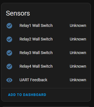
Fixed the above issue by swapping the latest uart_readline_sensor library (which I had) to the one that’s shared by @b6e7i9 .
That’s really brilliant. good to see your progess and I am happy to see the esp yaml. Have you had any physical mod to flash it? Any additional information that you can share? I really love the Tinxy app and the API integrations that’s provided but for my knowledge I want to check the esp on the device.
Can you share the steps that you have followed to integrate with HA? I have multiple Tinxy modes at my place and I want to integrate couple of them with HA via esphome. If you can share the initial flashing connection diagram and working yaml will be helpful. Since you have travelled the path already and made success, this will be helpful to others.
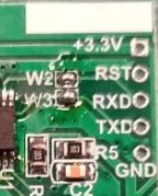
hi @sri4tinxy, first of all desolder the bridge w2 and w3 (refer image) from backside of tinxy board, then connect solder some wires from tinxy rxd, txd, 3.3v, gnd pads to usb ttl adaptor (swap the rxd txd connection). Use esptool to backup 4MB firmware, then flash the esphome firmware through espflasher software. Do remember to solder back the w2 and w3 bridges like before, remove the ttl wires and put back the sleeve. Now you can connect it to mains and home assistant will discover the new esphome device.
below is the code for Tinxy 4N with regulator with proper fan control and working manual switch delay.
esphome:
  name: tinxy-4node
  friendly_name: tinxy-4node
  on_boot:
    - priority: 200.0
      then:
        - output.turn_on: gen_pwm_test
        - output.set_level:
            id: gen_pwm_test
            level: 50%
  includes:
    - uart_read_line_sensor.h

output:
  - platform: esp8266_pwm
    id: gen_pwm_test
    pin: GPIO14
    frequency: 1000 Hz

  - platform: template
    id: fanoutput
    type: float
    write_action:
    - uart.write: ""


esp8266:
  board: esp01_1m

# Enable logging
logger:
  baud_rate: 0
  level: verbose

# Enable Home Assistant API
api:
  encryption:
    key:

ota:
  password:

wifi:
  ssid:
  password: !secret wifi_password
  power_save_mode: none
  fast_connect: true
  manual_ip:


  # Enable fallback hotspot (captive portal) in case wifi connection fails

status_led:
  pin:
    number: GPIO12
    inverted: yes

uart:
  id: uart_bus
  tx_pin: 1
  rx_pin: 3
  baud_rate: 9600

text_sensor:
  - platform: custom
    lambda: |-
      auto my_custom_sensor = new UartReadLineSensor(id(uart_bus));
      App.register_component(my_custom_sensor);
      return {my_custom_sensor};
    text_sensors:
      id: "uart_readline"
      name: "UART Feedback"
      on_value:
        then:
          - lambda: |-
              ESP_LOGD("main", "The current value is %s", x.c_str());

              if (id(uart_readline).state == "41") {
                id(relay4_wall_switch).publish_state(true);
                id(relay4).publish_state(true);
              } if(id(uart_readline).state == "40") {
                id(relay4_wall_switch).publish_state(false);
                id(relay4).publish_state(false);
              }
              if (id(uart_readline).state == "31") {
                id(relay3_wall_switch).publish_state(true);
                id(relay3).publish_state(true);
              } if(id(uart_readline).state== "30") {
                id(relay3_wall_switch).publish_state(false);
                id(relay3).publish_state(false);
              }
              if (id(uart_readline).state == "21") {
                id(relay2_wall_switch).publish_state(true);
                id(relay2).publish_state(true);
              } if(id(uart_readline).state== "20") {
                id(relay2_wall_switch).publish_state(false);
                id(relay2).publish_state(false);
              }
              if (id(uart_readline).state == "11") {
                id(relay1_wall_switch).publish_state(true);
                auto call = id(fan_1).turn_on();
                call.perform();
              } if(id(uart_readline).state== "10") {
                id(relay1_wall_switch).publish_state(false);
                auto call = id(fan_1).turn_off();
                call.perform();
              }

binary_sensor:
  - platform: template
    name: "Relay4 Wall Switch"
    id: relay4_wall_switch


  - platform: template
    name: "Relay3 Wall Switch"
    id: relay3_wall_switch


  - platform: template
    name: "Relay2 Wall Switch"
    id: relay2_wall_switch


  - platform: template
    name: "Relay1 Wall Switch"
    id: relay1_wall_switch

switch:
  - platform: template
    name: "Relay2"
    id: relay2
    optimistic: true
    restore_mode: RESTORE_DEFAULT_OFF
    turn_on_action:
      - uart.write: '#2100#'
    turn_off_action:
      - uart.write: '#2000#'

  - platform: template
    name: "Relay3"
    id: relay3
    optimistic: true
    restore_mode: RESTORE_DEFAULT_OFF
    turn_on_action:
      - uart.write: '#3100#'
    turn_off_action:
      - uart.write: '#3000#'

  - platform: template
    name: "Relay4"
    id: relay4
    optimistic: true
    restore_mode: RESTORE_DEFAULT_OFF
    turn_on_action:
      - uart.write: '#4100#'
    turn_off_action:
      - uart.write: '#4000#'

fan:
  - platform: speed
    output: fanoutput
    id: fan_1
    speed_count: 3
    name: "Fan"
    on_turn_on:
      - uart.write: !lambda |-
          static std::string myUartStringsOn[4] = {"#1100#", "#1033#", "#1066#", "#1100#"};
          if(id(fan_1).speed == 0)
            id(fan_1).speed = 1;
          std::string chosenString = myUartStringsOn[id(fan_1).speed];
          std::vector<uint8_t> vec(chosenString.begin(), chosenString.end());
          return vec;
    on_turn_off:
      - uart.write: '#1000#'

    on_speed_set:
    - if:
        condition:
          lambda: return (id(fan_1).state);
        then:
          - uart.write: !lambda |-
              static std::string myUartStringsOn[4] = {"#1100#", "#1033#", "#1066#", "#1100#"};
              std::string chosenString = myUartStringsOn[id(fan_1).speed];
              std::vector<uint8_t> vec(chosenString.begin(), chosenString.end());
              return vec;

number:
  - platform: template
    name: "Switch Delay"
    id: "switchdelay"
    optimistic: true
    restore_value: true
    initial_value: "60"
    min_value: 5
    max_value: 100
    step: 1
    set_action:
      then:
        - uart.write: !lambda |-
            int multiplexer = 625 + static_cast<int>((x - 5) * 25);
            String uartValue = "(";
            if (multiplexer < 1000) {
              uartValue += "0";
            }
            uartValue += String(multiplexer, DEC) + ")";
            std::vector<unsigned char> uartBytes(uartValue.begin(), uartValue.end());
            return uartBytes;
use the uart_read_line_sensor.h code mentioned in the earlier post. You are all set now.
Thanks a ton for your immediate reply with the image. I will try it out. ![]()
Finally I got a chance to flash single node 16A with esphome using below given code. I do understand that the single node work differently compared to 2N, 4N or 6N. Since 1N 's esphome YAML is not anywhere, I tried to modify it to fit with reference to your 4N code. While the node was still connected with UART, I was able to connect via the IP address of the device from browser and can push the relay switch to on or off. However after disconnecting the headers and connecting the node to AC Power, the LED on the Circuit + LED on the esp chip are blinking. On the ESPhome page its showing as online in HA but I can’t connect to that. What am I missing or doing wrong?
Note: As per your suggestion I have created uart_read_line_sensor.h with the codes shared by @b6e7i9 in the location /homeassistant/esphome/.
esphome:
  name: tinxy-1node-16a
  friendly_name: tinxy-1node-16a
  on_boot:
    - priority: 200.0
      then:
        - output.turn_on: gen_pwm_test
        - output.set_level:
            id: gen_pwm_test
            level: 50%
  includes:
    - uart_read_line_sensor.h

output:
  - platform: esp8266_pwm
    id: gen_pwm_test
    pin: GPIO14
    frequency: 1000 Hz

esp8266:
  board: esp01_1m

# Enable logging
logger:
  baud_rate: 0
  level: verbose

# Enable Home Assistant API
api:
  encryption:
    key: "removedtheactualvalue"

ota:
  password: "removedtheactualvalue"

wifi:
  ssid: !secret wifi_ssid
  password: !secret wifi_password
  manual_ip:
    static_ip: removedtheactualvalue
    gateway: removedtheactualvalue
    subnet: removedtheactualvalue
    dns1: removedtheactualvalue

  # Enable fallback hotspot (captive portal) in case wifi connection fails
  ap:
    ssid: "Tinxy-1Node-16A Fallback Hotspot"
    password: "removedtheactualvalue"

captive_portal:
web_server:
  port: 80

status_led:
  pin:
    number: GPIO12
    inverted: yes

uart:
  id: uart_bus
  tx_pin: 1
  rx_pin: 3
  baud_rate: 9600

text_sensor:
  - platform: custom
    lambda: |-
      auto my_custom_sensor = new UartReadLineSensor(id(uart_bus));
      App.register_component(my_custom_sensor);
      return {my_custom_sensor};
    text_sensors:
      id: "uart_readline"
      name: "UART Feedback"
      on_value:
        then:
          - lambda: |-
              ESP_LOGD("main", "The current value is %s", x.c_str());

              if (id(uart_readline).state == "11") {
                id(relay1_wall_switch).publish_state(true);
                id(relay1).publish_state(true);
              } if(id(uart_readline).state == "10") {
                id(relay1_wall_switch).publish_state(false);
                id(relay1).publish_state(false);
              }

  - platform: wifi_info
    ip_address:
      name: ESP IP Address
    ssid:
      name: ESP Connected SSID
    mac_address:
      name: ESP Mac Wifi Address

binary_sensor:
  - platform: template
    name: "Relay1 Wall Switch"
    id: relay1_wall_switch

switch:
  - platform: template
    name: "Relay1"
    id: relay1
    #pin: GPIO05
    optimistic: true
    restore_mode: RESTORE_DEFAULT_OFF
    turn_on_action:
      - uart.write: '#1100#'
    turn_off_action:
      - uart.write: '#1000#'

number:
  - platform: template
    name: "Switch Delay"
    id: "switchdelay"
    optimistic: true
    restore_value: true
    initial_value: "60"
    min_value: 5
    max_value: 100
    step: 1
    set_action:
      then:
        - uart.write: !lambda |-
            int multiplexer = 625 + static_cast<int>((x - 5) * 25);
            String uartValue = "(";
            if (multiplexer < 1000) {
              uartValue += "0";
            }
            uartValue += String(multiplexer, DEC) + ")";
            std::vector<unsigned char> uartBytes(uartValue.begin(), uartValue.end());
            return uartBytes;
For Completeness, I am providing the uart_read_line_sensor.h file details as well here. In case I have to amend anything in that file.
#include "esphome.h"

class UartReadLineSensor : public Component, public UARTDevice, public TextSensor {
 public:
  UartReadLineSensor(UARTComponent *parent) : UARTDevice(parent) {}

  void setup() override {
    // nothing to do here
  }

  int readline(int readch, char *buffer, int len)
  {
    static int pos = 0;
    int rpos;

    if (readch > 0) {
      switch (readch) {
        case ';': // Return on CR
          rpos = pos;
          pos = 0;  // Reset position index ready for next time
          return rpos;
        default:
          if (pos < len-1) {
            buffer[pos++] = readch;
            buffer[pos] = 0;
          }
      }
    }
    // No end of line has been found, so return -1.
    return -1;
  }

  void loop() override {
    const int max_line_length = 20;
    static char buffer[max_line_length];
    while (available()) {
      if(readline(read(), buffer, max_line_length) > 0) {
        publish_state(buffer);
      }
    }
  }
};
Same problem.
I am using tasmota. I have added this template for 16A 1 node.
{“NAME”:“Tnxy16A”,“GPIO”:[32,0,0,0,160,224,0,0,288,0,416,0,0,0],“FLAG”:0,“BASE”:18}
after that in console tried following commands
setoption15 0
setoption68 0
Pwmfrequency 1000
Pwmrange 1023
pwm1 512
Backlog rule on system#boot do pwm1 512 endon; Rule 1 1
as mention in below link
What is the problem you are facing with 16amp 1 node module? Depending on the problem, there is a solution in Tasmota Discussion board, discussion no. 17261 . (If the problem is constant rebooting after 220v is connected to the L port,)
I tried that as mention above but switch rebooting issue still persist. I applied that solution as mention discussion no 17261 above.
when i on the external switch it will cause problem.
Yes, this problem (When the external 220v switch is turned on the Tinxy16Amp 1Node starts to reboot) is a problem that has been resolved in that thread. If GPIO04 of the device is used as Switch-1 and mains live/220v is fed to the switch port of this device then the reset problem returns and device reboots every 15/30 seconds. Only solution is to not use Switch Port with mains Live/220vAC input which is assigned as switch-1 in tasmota, instead assign button-1 as Switch-1 on GPIO-0 to physically toggle on/off using 3.3vDC signalling and not use 220vAC for signalling on GPIO-4, you can assign GPIO-4 as button-1 or disable it. This involves physical modification of this device as you have to solder wires to GPIO-0 and extend these wires to your physical switch. (As mentioned in bottom posts of discussion# 17261 in Tasmota discussion board, look for replies given to sagarch888 and shivani446). However, this method will certainly void any manufacturer warranty and manufacturer will definitely wash their hands off from any future problems. I hope this helps.
I have one question in default firmware gpio 4 use as switch which works fine. So what could be problem with tasmota when we apply 220v AC on gpio 4 which cause problem.
1 Like
Thanks for raising this. I too have the same doubt. Is the software level On/Off done via “uart.write” method instead of GPIO?
In 16A 1 node tinxy i tried by given 3.3v input to optocoupler directly extenal source while main switch is disconnect from the tinxy switch. I bypass the switch input and given 3.3v to optocoupler. when i give 3.3v load is on and when disconnect 3.3v from input of optocoupler load get off.
So basically issue i found is that at input of optocoupler i get 1.01v when operating with switch. so i given it directly using 3.3v supply.
So, my question is that is it still tasmota side issue because when we given 3.3v it works fine ?
Apart from it i tried many registor’s(R12) to increase 1.01v to 1.5v around or more. but every time i get same voltage drop across optocoupler.
registor i tried upto 100K instead of R12 .
have anyone idea why this happen it drop always same voltage around 1.01v or any one have different suggestion for it. how to overcome this issue ?
Hey @mohit
I tried to flash esphome with my working code on 4N and the uart doesn’t seem to work. I mean, the transfer happens but the the actual relay triggering doesn’t seem to work. did something change recently? ‘#1100#’/#1000# commands are still the same? I tried the same on two new boards. first one i thought something went wrong during my flashing process, but second board I was very careful. I bridged W4 to prevent the reset from happening and flashed it successfully, esp comes online no issues but the uart seems broken. W2&W3 are connected back as well. Anything changed recently?
Thanks!
Update: I was able to fix it. Turns out that the baud rate is 115200 for new models. Thanks to @mohit ! Also the pwm needs to be generated much earlier than 200. just fyi, for future reference.
Hi everyone
I was trying to flash a 4N with Regulator with ESPHome but a strange thing is observed. As the flash is erased and new firmware is being written, the device stops responding at about 30% progress. The device gets stuck at this point and never recovers. Now if the process is restarted, same thing occurs.
JFYI, I have flashed plenty nodes in the past and aware of MCU bridge desoldering and connections to the ESP module. Am I missing something with the new devices? Something that needs to be done differently?
@mohit Could you kindly guide on the above issue?
Thanks in advance.
1 Like
There a track going to ESP8266 RST pin from CH32 MCU, just cut that track. you should be fine after that.