Thanks for the pointer @mohit
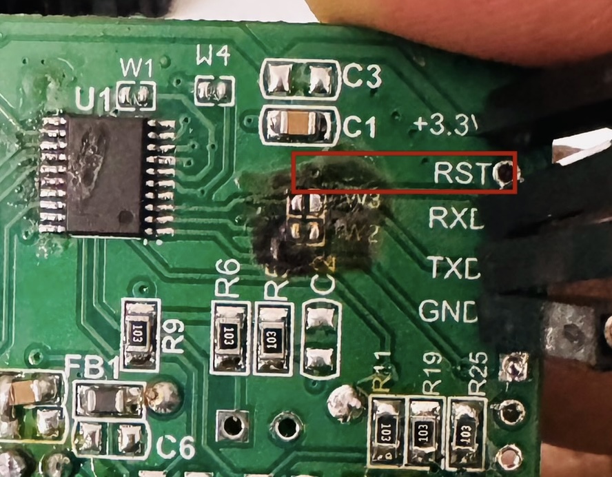
I am attaching a photo for reference. Am I looking at the right track?
Also should the track be soldered/joined back after flashing the custom firmware?
Thanks for the pointer @mohit
I am attaching a photo for reference. Am I looking at the right track?
Also should the track be soldered/joined back after flashing the custom firmware?
The RST hole in the image is for programming. This is wrong. The MCU you see is in the left is CH32 . Use multimeter to find the conection between ESP8266 RST pin on the wifi chip and CH32 pin
Thanks for the pointer @mohit
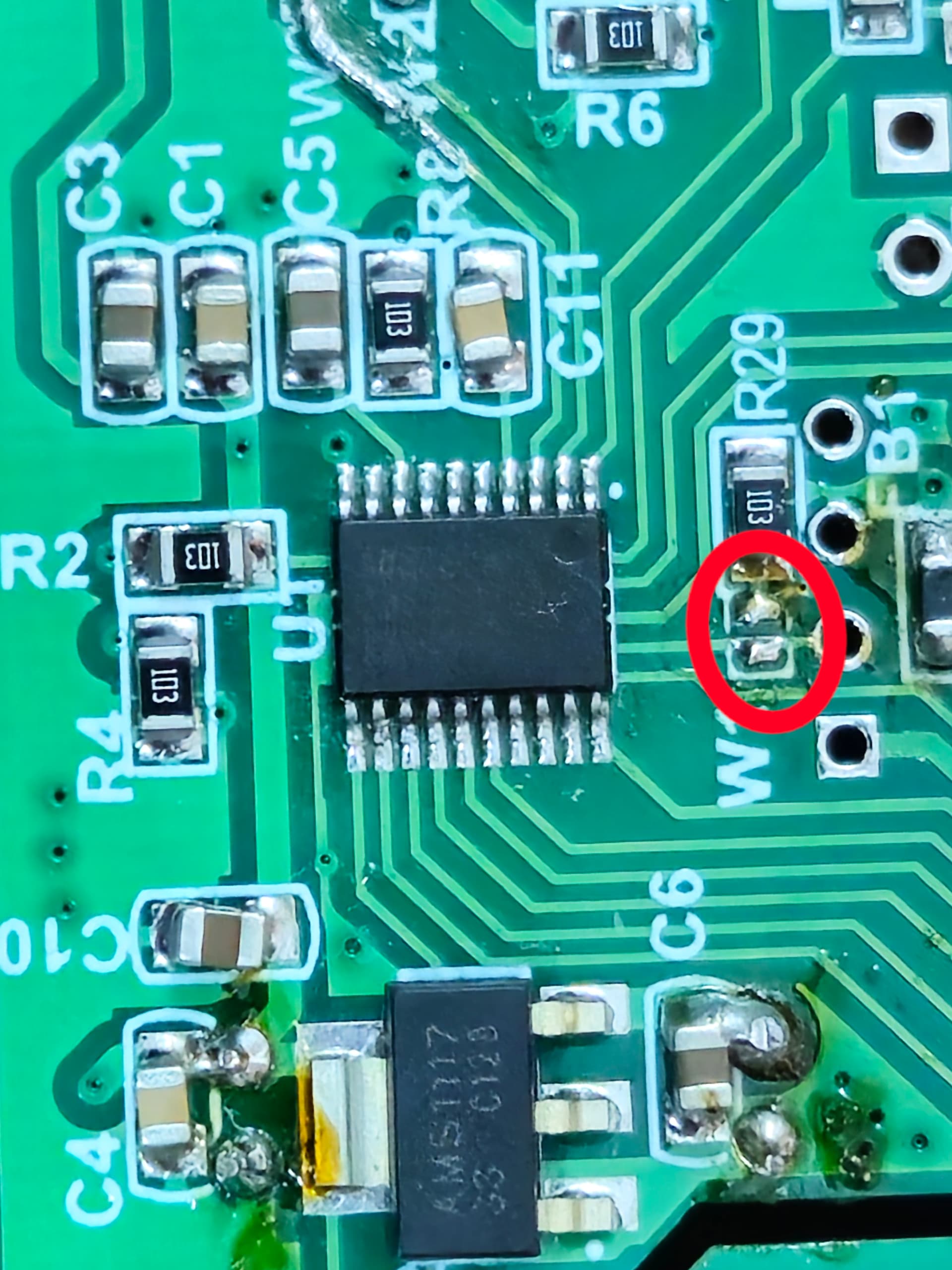
I have checked with a multimeter and the RST Pin / RST Hole on ESP8266 is connected with Pin # 5 on the right hand-side of the MCU. The track is going towards the bridge point W1.
Do you suggest cutting the track near the MCU or near the W1 bridge?
I am seeing a similar arrangement on the 4 nodes unit procured recently. Do you recommend performing a similar procedure on the 4 nodes unit too?
Getting a bit nervous as I had procured 5 units in total to retrofitting after observing the long term performance of the products installed about 2 years ago.
We had a small batch of devices which has the incorrect firmware for the offline MCU . So either you send us the faulty ones , we can upgrade firmware or you can just cut the track to resolve the issue. Your devices would work perfectly fine. Don’t worry. Also we provide unlimited manufacturer defect warranty in most cases.
Mohit
Share your phone number on mohit@tinxy.in .
Thank you for sharing the information.
I am impressed by the commitment your company shows towards its products and customers, particularly the lifetime warranty for manufacturing defects. It speaks volumes about your dedication to quality and customer satisfaction.
I have shared my contact details over email as requested. Cheers.
Hi All, I have installed ESPHome on 16amp 1N board with pwm (50% duty cycle) on boot. Device turns on fine, no restart issues. However, turning switch on (with GPIO4) from HA doesn’t activate the relay. Is there any known issue with this board or additional settings required? Please guide here.
Hi Brijin, please tell me the priority that u set. I have flashed esphome on 16 amp 1N board but switching is not happening. Please look at the last post by me in this forum.
Hi,
Here is the priority I set for a recent purchase (4N).
esphome:
  name: lwash
  on_boot:
    - priority: 600.0
      then:
        - output.turn_on: gen_pwm_test
        - output.set_level:
            id: gen_pwm_test
            level: 50%
Please share your yaml file
Hi Brijin, thanks for sharing the details. Switch configured in Home Assistant is able to turn on/off the relay via GPIO5.
I have a binary GPIO sensor on GPIO4 to know the state of physical switch. The moment I turn the physical switch on, binary sensor starts publishing on-off continuously and relay also doesn’t turn on. I have not been able to explore the circuit much hence not able to understand this behavior.
Any insight on understanding the physical switch feedback to ESP would help a lot.
CC: @mohit
@amithkk you should have a filter for the binary sensor (delayed_off for 500ms, I haven’t tried any other values, this started working so I didn’t bother to change it). Here is an example snippet, you could adopt it on your code, see if it works,
binary_sensor:
  - platform: gpio
    pin:
      number: GPIO4
      mode: INPUT_PULLUP
      inverted: true
    name: "Bedroom1 Bathroom Bulb Wall Switch"

    filters:
      - delayed_off: 500ms

    on_press:
        then:
          - switch.turn_on: b1bathroom_bulb_power

    on_release:
        then:
          - switch.turn_off: b1bathroom_bulb_power
Thanks Brijin … i will try and let you know. I had read some article also and was planning to add filter
Thanks Brijin!! adding delayed-off filter made it work!
Hi @b6e7i9 have u programmed 6N board recently? I programmed one yesterday and able to upload esphome on it. After uploading, I had to keep W1 bridge (as seen in attached photo) open else board was not working properly. I connected load on one of the port and tried switching it on-off. Switching worked some time but some time it didn’t. Not sure whether issue is with UART text sensor or baud rate (used 9600). Same UART sensor code is working fine with 2N board. Please share your insight if u faced similar issue in past.
@aspofficial94 I saw one of ur post where u were trying to flash a 6N board. Did it work end to end. Please share ur thought on the problem shared above.
115200 is the baud rate used on newer boards. just connect the bridges back to stock, it should work.
My board is working with 9600 baud rate. I found that relay MCU is not accepting the ‘on’ command like #6100# but it accepted #6000# and turned off the relay.
Custom UART text sensor is working fine and is able to interprete on/off commands sent by MCU without any issue. Has the ‘on’ command string (e.g., #6100#) changed for some boards?
I tried followimg combination for ‘on’ command but no success -
#6101#
#6111#
#6110#
Issue got resolved by using UART1 for logger module
Has anyone figured out how to get external switch state after boot?
Did you figure this out? I am facing the same issue